1. Einleitung
This manual provides detailed instructions for assembling and operating your ICSTATION Heart Shaped LED Light Soldering Project Kit. Designed for beginners and electronics enthusiasts, this kit offers a practical way to enhance soldering skills while creating a decorative LED light display. Please read all instructions carefully before beginning assembly.
2. Lieferumfang
Vergewissern Sie sich vor Beginn der Montage, dass alle unten aufgeführten Komponenten in Ihrem Bausatz vorhanden sind.

Image: All components included in the Heart Shaped LED Light Soldering Project Kit, laid out for inspection.
- Heart-shaped PCB (Printed Circuit Board)
- 32 RGB-LEDs
- STC89C58RD Microcontroller
- DIP40 IC Socket
- Widerstände (verschiedene Werte)
- Capacitors (various values)
- Quarzoszillator
- Netzschalter
- Battery Holder (for 2x AAA batteries)
- Acrylic Case components (front, back, stand)
- Schrauben
- Verbindungskabel
3. Sicherheitshinweise
Warnung: This kit involves soldering, which uses high temperatures and can produce fumes. Always follow these safety guidelines:
- Arbeiten Sie in einem gut belüfteten Bereich, um das Einatmen von Lötrauch zu vermeiden.
- Wear safety glasses to protect your eyes from splashes or flying debris.
- Verwenden Sie einen Lötkolbenständer, um versehentliche Verbrennungen zu vermeiden.
- Ensure the soldering iron is unplugged and cooled down when not in use.
- Halten Sie brennbare Materialien von Ihrem Arbeitsbereich fern.
- Nach dem Umgang mit Lötzinn gründlich die Hände waschen.
- Keep out of reach of children unless under direct adult supervision.
4. Aufbau und Montage
This section guides you through the assembly process. A soldering iron, solder, and basic tools like wire cutters and needle-nose pliers are required (not included in this kit).
4.1. Vorbereitung
- Packen Sie alle Komponenten aus und überprüfen Sie den Inhalt anhand der Liste „Was ist in der Box?“.
- Prepare your soldering workstation with adequate ventilation and lighting.
- Familiarize yourself with the PCB layout and component placement.
4.2. Löten von Bauteilen
Solder components in order from smallest to largest to ensure easier access. Start with resistors, then capacitors, crystal, and finally the IC socket and LEDs.
- Widerstände: Identify the resistors by their color codes or markings. Insert them into their designated positions (R1-R32) on the PCB. Bend the leads on the underside to hold them in place, then solder and trim excess leads.
- Capacitors and Crystal: Solder the small ceramic capacitors and the crystal oscillator into their respective positions. Ensure the crystal is securely seated.
- Microcontroller Socket: Place the DIP40 IC socket onto the PCB, aligning the notch on the socket with the notch on the PCB silkscreen. Solder all pins. This socket allows for easy insertion/removal of the microcontroller.
- LEDs: Carefully insert each of the 32 RGB LEDs into their designated holes. LEDs are polarized; ensure the longer lead (anode) goes into the hole marked with a '+' or the square pad, and the shorter lead (cathode) goes into the round pad. Solder each LED and trim the leads.
- Stromschalter: Solder the power switch into its position.
- Battery Holder Wires: Connect the red wire from the battery holder to the '+' pad and the black wire to the '-' pad on the PCB.

Image: Close-up of the heart-shaped PCB with resistors correctly soldered into place.
4.3. Microcontroller Installation
Gently insert the STC89C58RD microcontroller into the soldered IC socket. Ensure the notch on the microcontroller aligns with the notch on the socket and PCB. Apply even pressure to avoid bending pins.
4.4. Montage des Acrylgehäuses
- Remove the protective film from all acrylic pieces.
- Attach the stand piece to the bottom of one heart-shaped acrylic cover using the provided screws.
- Carefully place the assembled PCB into the acrylic cover with the stand.
- Align the second acrylic cover on top and secure it with the remaining screws. Ensure the power switch is accessible.
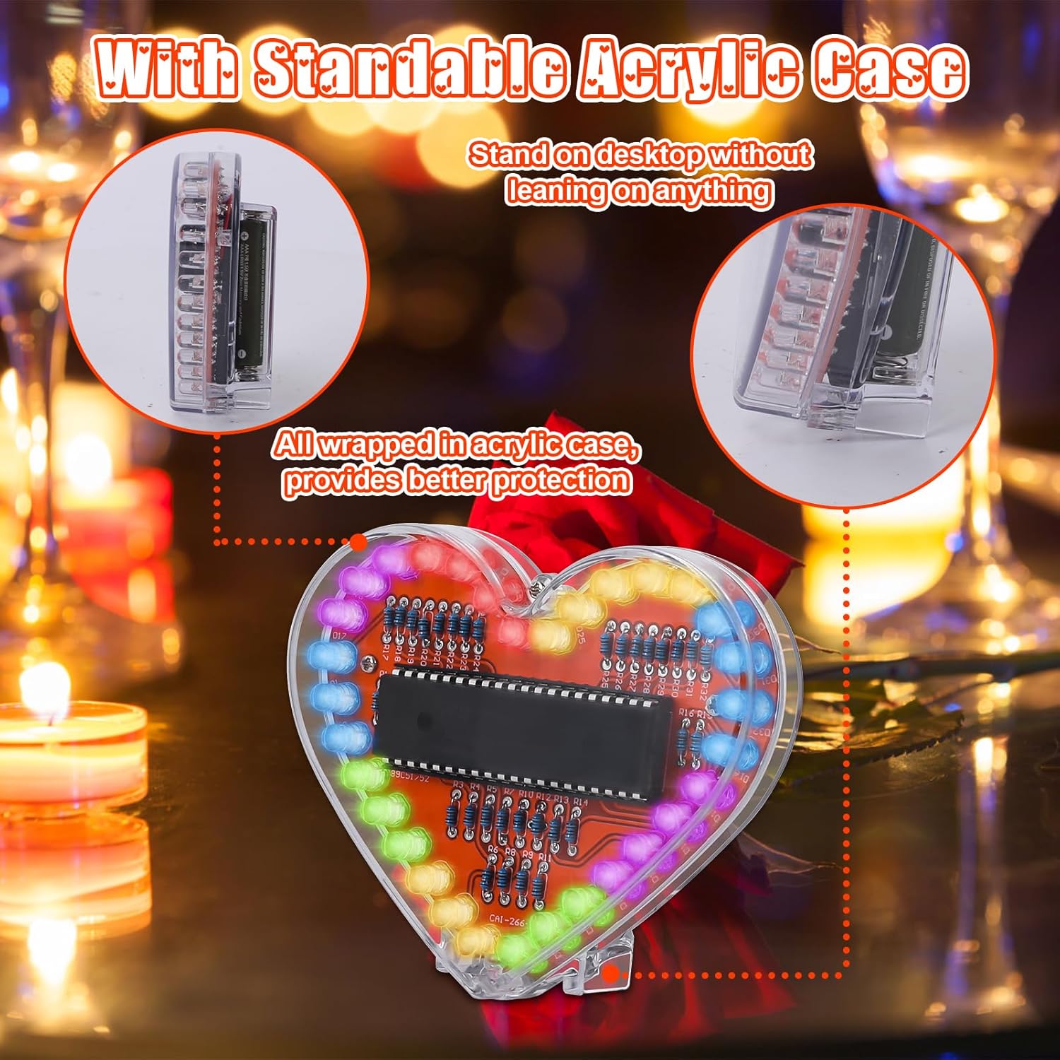
Image: The finished heart-shaped LED light enclosed in its standable acrylic case.
4.5. Einlegen der Batterie
Insert two AAA batteries (not included) into the battery holder, observing correct polarity (+/-). The device is now ready for operation.

Image: Close-up of the battery compartment, showing where to insert two AAA batteries.
4.6. Montage-Videoanleitung
Eine visuelle Anleitung zum Montageprozess finden Sie im offiziellen Produktvideo unten:
Video: Official product video demonstrating the assembly and features of the Heart Shaped LED Light Soldering Project Kit.
5. Bedienungsanleitung
Once assembled and batteries are installed, operating the Heart Shaped LED Light is straightforward.
- Einschalten: Locate the power switch on the side or bottom of the acrylic case. Slide the switch to the "ON" position.
- Lichtanzeige: The 32 RGB LEDs will immediately begin to display a variety of colorful patterns and effects. The microcontroller is pre-programmed with multiple light show sequences.
- Ausschalten: To turn off the device, slide the power switch to the "OFF" position.

Image: The assembled heart-shaped LED light showcasing its dynamic rainbow LED light show.
6. Wartung
- Reinigung: Use a soft, dry cloth to gently wipe the acrylic case. Avoid abrasive cleaners or solvents.
- Batteriewechsel: If the LED light show becomes dim or stops working, replace the two AAA batteries. Ensure correct polarity.
- Lagerung: Store the kit in a cool, dry place away from direct sunlight and extreme temperatures. If storing for extended periods, remove the batteries to prevent leakage.
- Komponenteninspektion: Periodically check soldered joints for any signs of corrosion or loose connections. Re-solder if necessary.
7. Fehlerbehebung
| Problem | Mögliche Ursache | Lösung |
|---|---|---|
| LEDs leuchten nicht. |
|
|
| Einige LEDs leuchten nicht. |
|
|
| Light patterns are erratic or incorrect. |
|
|
8. Spezifikationen
| Besonderheit | Detail |
|---|---|
| Modellnummer | GY21248-2 |
| Abmessungen (L x B x H) | 1.18 x 3.07 x 1.18 Zoll |
| Artikelgewicht | 1.76 Unzen |
| LED-Typ | RGB LEDs (32 count) |
| Stromquelle | 2 x AAA-Batterien (nicht enthalten) |
| Mikrocontroller | STC89C58RD |

Image: Diagram showing the dimensions of the assembled Heart Shaped LED Light.
9. Garantie und Support
Specific warranty information for this product is not provided in the available data. For any technical support, missing parts, or inquiries regarding your ICSTATION Heart Shaped LED Light Soldering Project Kit, please contact the manufacturer or seller directly through the platform where the product was purchased.
Manufacturer: ICSTATION


