1. Einleitung
This manual provides detailed instructions for the Waveshare Industrial 8-Channel Analog Output Module. This module is designed for industrial applications, offering 8-channel simultaneous current or voltage output with 12-bit DA conversion. It supports the Modbus RTU protocol via RS485 communication and features a wide voltage power supply range of DC 7~36V. The module incorporates multiple isolation and protection circuits for enhanced reliability and stability in demanding environments.
Key features include a configurable device address, onboard voltage regulator, unibody power supply and magnetic isolation, resettable fuse, TVS (Transient Voltage Suppressor), 12-bit DA conversion, an onboard watchdog, and a rail-mount case design for easy installation.

Bild 1.1: Überview of the Industrial 8-Channel Analog Output Module.
2. Packungsinhalt
Bitte prüfen Sie, ob alle unten aufgeführten Artikel in Ihrem Paket enthalten sind. Sollten Artikel fehlen oder beschädigt sein, kontaktieren Sie bitte Ihren Lieferanten.
- Modbus RTU Analog Output 8CH Module x1
- Netzteil-Anschlussadapter x1
- Schraubendreher x1

Image 2.1: Contents of the product package, including the module, power adapter, and screwdriver.
3. Funktionen auf einen Blick
- Configurable Device Address: Supports addresses from 1 to 255, allowing multiple devices to be cascaded on an RS485 bus.
- Breites Volumentage Stromversorgung: Bordlautstärketage regulator supports a 7~36V DC power supply range.
- Isolierung der Stromversorgung: Unibody power supply isolation provides stable isolated voltage ohne dass eine zusätzliche Stromversorgung für den isolierten Anschluss erforderlich ist.
- Magnetische Isolierung: Unibody magnetic isolation ensures signal isolation, high reliability, and strong anti-interference capabilities.
- Verbesserter Schutz: Onboard resettable fuse and TVS (Transient Voltage Suppressor) effectively suppress surge voltage und transiente Spike-Voltage, offering over-current/over-voltage protection, lightning protection, and anti-electrostatic discharge (ESD) capabilities.
- High-Precision DA Conversion: 12-bit DA conversion utilizes high-precision resistors for accurate output data.
- Überwachungsfunktion: Onboard watchdog ensures stable output operation without system crashes.
- Schienenmontage-Design: Rail-mount case design supports stacking combinations, facilitating easy installation and secure usage.
- Statusanzeigen: Three LEDs indicate MCU status and signal transceiving status.

Image 3.1: Visual representation of the module's key features.
4. Version Options
The module is available in two main versions, differing in their analog output capabilities:
- Modbus RTU Analog Output 8CH: Provides 8-channel current output with a range of 0-20mA.
- Modbus RTU Analog Output 8CH (B): Provides 8-channel voltage output with a range of 0-10V.

Image 4.1: Illustration of the two available module versions: current output (0-20mA) and voltage output (0-10V).
5. Primary Function
The primary function of this module is to support sending Modbus RTU protocol commands via RS485, enabling it to output data to 0-10V or 0-20mA sensors and control valves. This allows for integration into industrial control systems for precise analog control.
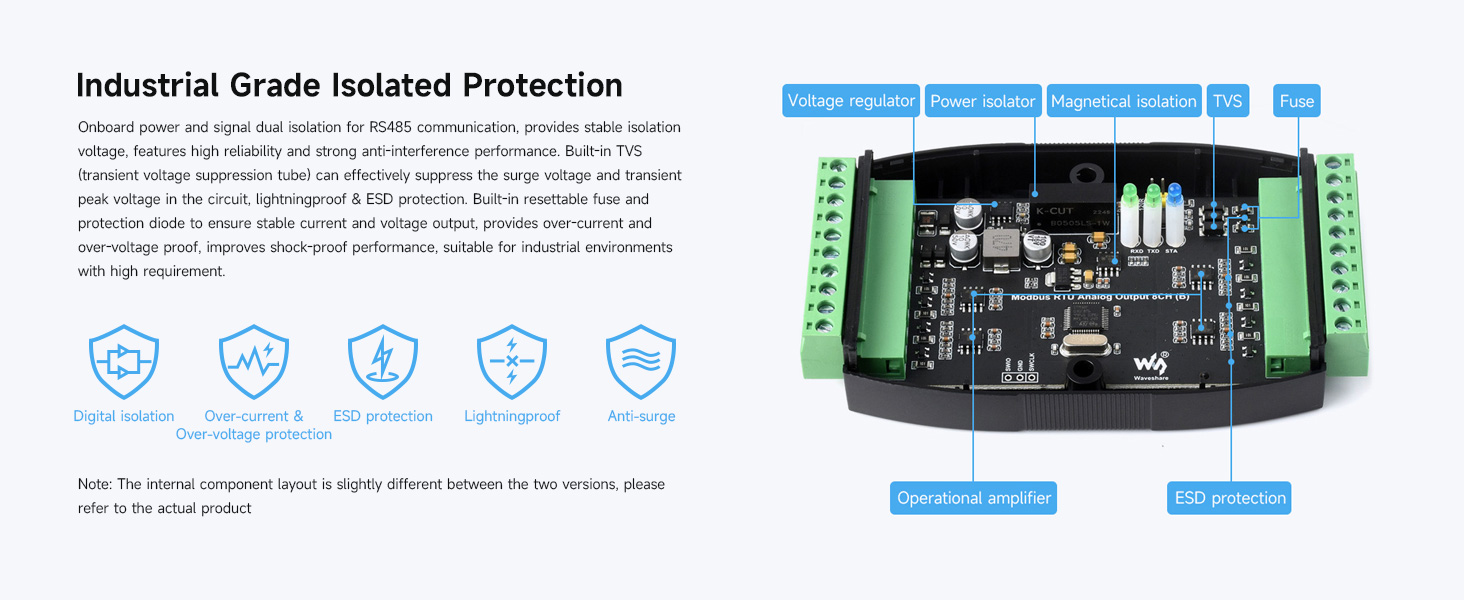
Image 5.1: Diagram illustrating the module's role in communicating with a host and controlling a valve via RS485.
6. Spezifikationen
The following table details the technical specifications for both versions of the Waveshare Industrial 8-Channel Analog Output Module.
| Parameter | Modbus RTU Analog Output 8CH | Modbus RTU Analog Output 8CH (B) |
|---|---|---|
| Kommunikationsschnittstelle | RS485 | |
| Baudrate | 4800, 9600, 19200, 38400, 57600, 115200, 128000, 256000 | |
| Standardkommunikationsformat | 9600, N, 8, 1 | |
| Modbus-Protokoll | Standard Modbus RTU-Protokoll | |
| Stromversorgung | DC 7-36V | |
| Ausgabe | 8-ch current output | 8-Kanal-Bandtage Ausgabe |
| Auflösung | 12-bit, 1µA | 12-bit, 1mV |
| Reichweite | 0-20 mA | 0 bis 10 V |
| Ausgabegenauigkeit | ± 0.03 mA | ±0.01 V |
Image 6.1: Detailed specifications for both current and voltage output versions of the module.
7. Industrial Grade Isolated Protection
The module is equipped with robust industrial-grade isolation and protection features to ensure stable and reliable operation in harsh environments. These include:
- Power and Signal Dual Isolation: Provides stable isolation voltage for RS485 communication, enhancing reliability and anti-interference.
- Built-in TVS: Übergangsvoltage Suppression tube effectively suppresses surge voltage und transiente Spike-Voltage.
- Lightningproof & ESD Protection: Safeguards against electrical surges and electrostatic discharge.
- Resettable Fuse and Protection Diode: Ensures stable current and voltage output, providing over-current and over-voltage proof.
- Shock-proof Performance: Designed for durability in industrial settings.

Abbildung 7.1: Intern view highlighting the various protection components such as voltage regulator, power isolator, magnetic isolation, TVS, and fuse.
8. Interface Introduction & Wide Voltage Netzteil
The module features clearly labeled interfaces for power, RS485 communication, and analog outputs. It supports a wide DC input voltage range of 7-36V and includes built-in fuse and anti-reverse protection, along with power and signal dual isolation for the RS485 interface.

Abbildung 8.1: Detailansicht view of the module's interfaces, including power input, RS485 terminals, analog output terminals, and status indicators (RX, TX, STATUS).
9. Industrial High-Precision Analog Output
The module provides 8 channels of high-precision analog output, utilizing 12-bit DA conversion. This ensures accurate and reliable control signals for various industrial applications. The current output version offers a 0-20mA range, while the voltage output version provides a 0-10V range.

Image 9.1: Illustration of the 8-channel current output (0-20mA) and voltage output (0-10V) configurations.
10. Anschlussdiagramm
The module supports setting device addresses (1-255) for multi-device cascading on the RS485 bus. It also supports both voltage and current analog output connections. Refer to the diagrams below for proper wiring.
- Stromversorgung: Connect DC 7-36V to the power input terminals.
- RS485-Verbindung: Connect the A+ and B- terminals to your PC or PLC's RS485 interface.
- Analogausgang: Connect your load (e.g., control valve, sensor) to the AOX and AGND terminals for each channel.

Image 10.1: Comprehensive connection diagram showing power, RS485, and analog output wiring for single and cascaded modules.
11. Rail-Mount Support & Stacking Installation
The module is designed for easy installation on a standard 35mm guide rail using its integrated rail-mount buckle. For applications requiring multiple modules in a compact space, stacking installation is supported.
- Rail-Mount: Secure the module onto a 35mm DIN rail using the built-in buckle.
- Stapeln: To stack modules, remove the rail-mount buckle from the outer module, then assemble the two modules together using screws.
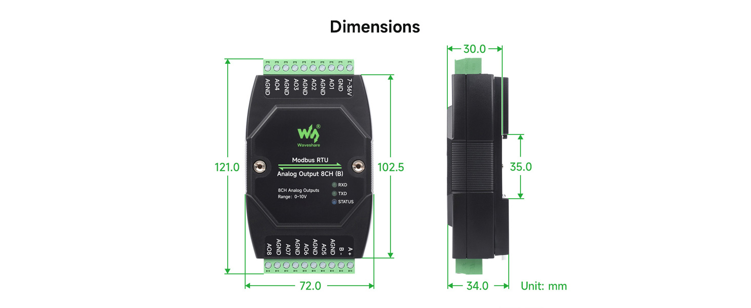
Image 11.1: Visual guide for mounting the module on a 35mm DIN rail and stacking multiple modules.
12. Abmessungen
The physical dimensions of the module are provided below for planning installation space. All units are in millimeters (mm).

Abbildung 12.1: Vorder-, Seiten- und Draufsicht views with dimensions (e.g., 121.0mm length, 72.0mm width, 34.0mm depth).
13. Einrichtung
Follow these steps for the initial setup of your Waveshare Industrial 8-Channel Analog Output Module:
- Montage: Securely mount the module on a 35mm DIN rail or in your desired enclosure. If stacking multiple modules, follow the stacking installation instructions.
- Stromanschluss: Connect a DC 7-36V power supply to the module's power input terminals (7-36V and GND). Ensure correct polarity.
- RS485-Verbindung: Connect the RS485 A+ and B- terminals of the module to your host device (PC, PLC, etc.) using a suitable RS485 cable. Ensure proper termination if required by your RS485 network.
- Analogausgangsanschluss: Connect your analog loads (e.g., control valves, actuators, meters) to the respective AOX and AGND terminals for each of the 8 channels. Ensure the load impedance is compatible with the module's output type (current or voltagUnd).
- Device Address Configuration: If using multiple modules on the same RS485 bus, configure a unique Modbus device address (1-255) for each module. Refer to the module's specific Modbus protocol documentation for details on how to set the address (typically via software commands or DIP switches, if present).
- Erstes Einschalten: Apply power to the module. Observe the LED indicators (RX, TX, STATUS) to confirm proper operation.
14. Betrieb
Operating the Waveshare Industrial 8-Channel Analog Output Module involves communicating with it via Modbus RTU protocol to control its analog outputs.
- Modbus-Kommunikation: Use a Modbus master device (e.g., PLC, industrial PC with Modbus software) to send commands to the module via the RS485 interface.
- Baud Rate and Format: Ensure your Modbus master is configured with the correct baud rate (e.g., 9600 bps) and communication format (e.g., N, 8, 1) as specified in the module's documentation.
- Writing Output Values: To set an analog output, send a Modbus write command to the corresponding register address for the desired channel. The value written will be a 12-bit digital value that the module converts to an analog current (0-20mA) or voltage (0-10V) output. Refer to the module's Modbus register map for specific addresses and data formats.
- Überwachungsstatus: The RX and TX LEDs indicate data reception and transmission, respectively. The STATUS LED provides general operational status.
- Multi-Device Operation: If multiple modules are cascaded, address each module individually using its configured device address in your Modbus commands.
15. Wartung
To ensure the longevity and reliable performance of your module, consider the following maintenance guidelines:
- Umgebungsbedingungen: Operate the module within its specified temperature and humidity ranges. Avoid exposure to excessive dust, moisture, or corrosive substances.
- Reinigung: If necessary, gently clean the module's exterior with a soft, dry cloth. Do not use harsh chemicals or abrasive materials.
- Verbindungsintegrität: Periodically inspect all wiring connections (power, RS485, analog outputs) to ensure they are secure and free from corrosion or damage.
- Firmware-Updates: Überprüfen Sie die Angaben des Herstellers website for any available firmware updates that may improve performance or address known issues. Follow update instructions carefully.
- Schutzfunktionen: The module includes resettable fuses and TVS for protection. In case of an over-current or over-voltage event, the resettable fuse may trip. Allow time for it to reset. If issues persist, investigate the cause of the electrical fault.
16. Fehlerbehebung
If you encounter issues with your Waveshare Industrial 8-Channel Analog Output Module, refer to the following troubleshooting steps:
- Keine Stromversorgung/Modul reagiert nicht:
- Verify the DC 7-36V power supply is connected correctly and providing the specified voltage.
- Check for blown fuses in the power supply circuit or if the module's internal resettable fuse has tripped.
- Stellen Sie sicher, dass alle Stromanschlüsse fest sitzen.
- Modbus Communication Failure:
- Confirm RS485 A+ and B- wiring is correct and not reversed.
- Verify that the Modbus master's baud rate and communication format match the module's settings.
- Check the module's device address and ensure it is unique on the bus and matches the address used by the Modbus master.
- Ensure RS485 termination resistors are correctly applied if needed for your network topology.
- Observe the RX/TX LEDs for activity. If no activity, check the RS485 cable and master device.
- Incorrect Analog Output:
- Verify that the correct digital value is being written to the Modbus register for the desired analog output.
- Ensure the load connected to the analog output is compatible with the module's output type (current or voltage) and range.
- Check the wiring to the analog load for shorts or open circuits.
- While the module uses high-precision resistors, some users have noted potential for output drift. If precise calibration is critical, consider external calibration or compensation in your control system.
- Module Freezing/Unresponsive:
- The onboard watchdog should prevent crashes. If the module becomes unresponsive, power cycle it.
- Stellen Sie sicher, dass die Stromversorgung stabil ist und innerhalb der angegebenen Lautstärke liegttage Reichweite.
17. Garantie und Support
Waveshare products typically come with a standard manufacturer's warranty covering defects in materials and workmanship. For specific warranty terms, duration, and conditions, please refer to the warranty information provided with your purchase or visit the official Waveshare webWebsite.
For technical support, troubleshooting assistance, or inquiries regarding product functionality, please contact Waveshare customer service or visit their support portal. Provide your product model number (8-Ch Analog Output Module) and any relevant purchase details when seeking support.


