1. Einleitung
This manual provides essential information for the installation, operation, and maintenance of the Cisco IE-3400-8T2S-E Catalyst IE3400 Rugged Series Network Essential Switch. This device is designed for industrial environments, offering robust network connectivity. Please read this manual thoroughly before operating the device.
2. Sicherheitshinweise
Beachten Sie die folgenden Sicherheitsvorkehrungen, um Verletzungen und Schäden am Gerät zu vermeiden:
- Stellen Sie sicher, dass das Gerät ordnungsgemäß geerdet ist.
- Vor Durchführung von Wartungs- oder Installationsarbeiten die Stromzufuhr unterbrechen.
- Operate the switch within the specified environmental conditions (temperature, humidity).
- Die Installation und Wartung dieser Geräte sollte ausschließlich von qualifiziertem Fachpersonal durchgeführt werden.
- Vermeiden Sie es, das Gerät Feuchtigkeit oder extremen Temperaturen auszusetzen.
3. Packungsinhalt
Überprüfen Sie, ob Ihr Paket die folgenden Artikel enthält:
- Cisco IE-3400-8T2S-E Catalyst IE3400 Rugged Series Network Essential Switch
- Dokumentation (Schnellstartanleitung, Sicherheitshinweise)
- Montagezubehör (sofern bei der jeweiligen Modellvariante enthalten)
- Power connector terminal blocks
Falls Artikel fehlen oder beschädigt sind, kontaktieren Sie umgehend Ihren Lieferanten.
4. Körperliche Übergriffeview
The following diagram illustrates the front panel components of the Cisco IE-3400-8T2S-E switch.
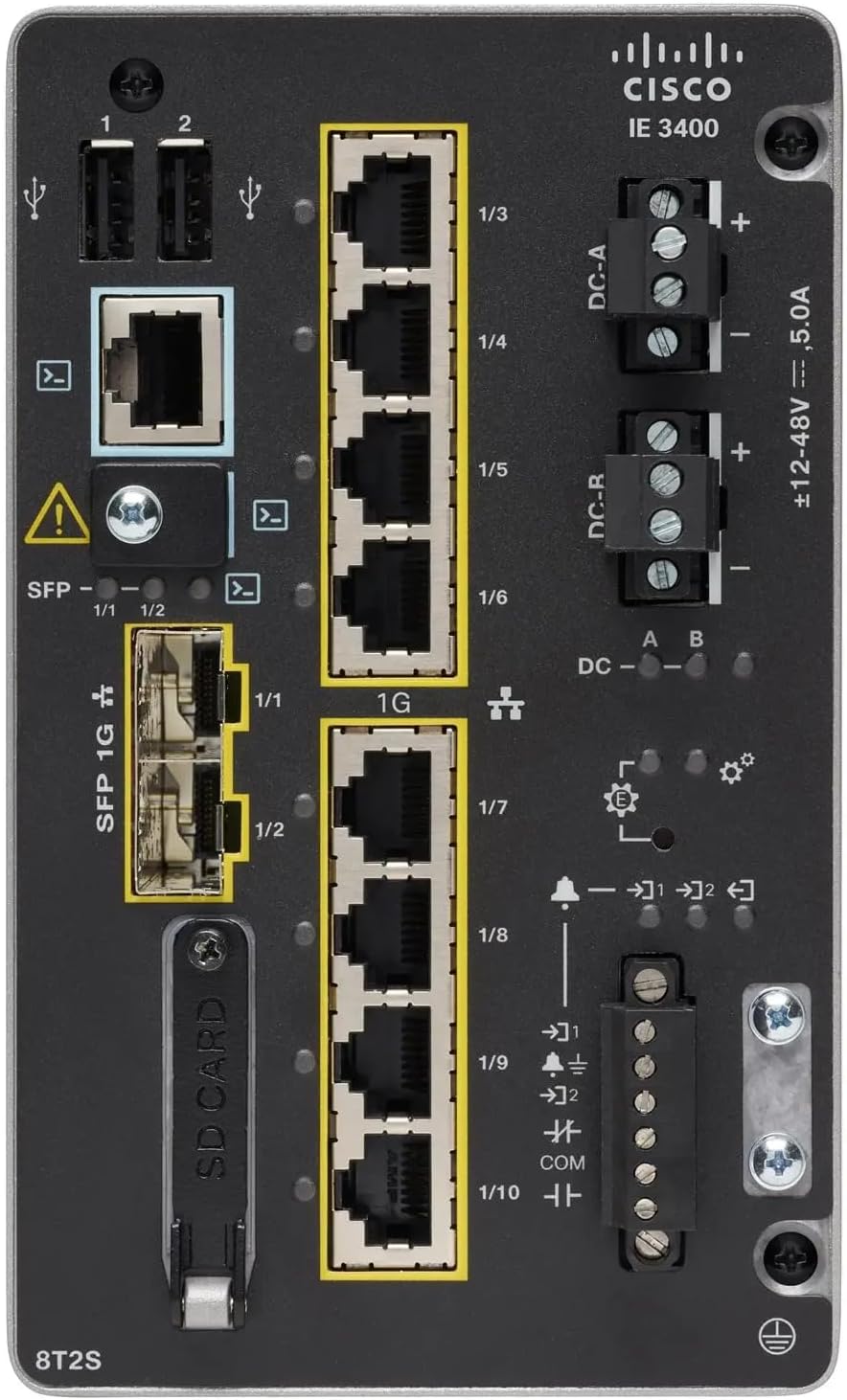
Abbildung 1: Front Panel Layout of the Cisco IE-3400-8T2S-E Switch
4.1. Front Panel Components Description
- USB-Anschlüsse (1, 2): Two USB ports for connecting external devices or for configuration.
- Konsolenport: An RJ45 console port for local management and initial configuration.
- SFP 1G Ports (1/1, 1/2): Two Small Form-Factor Pluggable (SFP) ports supporting 1 Gigabit Ethernet for fiber optic connections.
- 1G Ethernet Ports (1/3 - 1/10): Eight 1 Gigabit Ethernet RJ45 ports for standard network connections.
- DC Power Inputs (DC-A, DC-R): Redundant DC power input terminals, supporting a voltage range of ±12-48V at 5.0A.
- Erdungsschraube: Terminal for connecting the chassis to earth ground.
- SD-Kartensteckplatz: Slot for an SD card, typically used for configuration backup or software storage.
- Alarm/Relay Ports (1/9, 1/10): Terminals for connecting external alarm systems or relay controls.
- LED-Anzeigen: Various LEDs indicating power status (DC A/B), system status, link/activity for ports, and alarm status.
5. Einrichtung
5.1. Montage des Schalters
The IE3400 series switches are designed for industrial environments and typically support DIN rail or wall mounting. Refer to the specific mounting instructions provided with your mounting kit for detailed steps.
5.2. Stromversorgung anschließen
- Stellen Sie sicher, dass die Stromquelle ausgeschaltet ist, bevor Sie die Anschlüsse vornehmen.
- Connect the DC power cables to the DC-A and/or DC-R terminal blocks, observing polarity (+ and -). The switch supports redundant power inputs.
- Connect the grounding wire to the grounding screw on the front panel.
- Once all connections are secure, apply power to the switch. The DC-A and/or DC-B LEDs should illuminate.
5.3. Netzwerkverbindungen
- Ethernet-Ports: Connect standard RJ45 Ethernet cables from your network devices to the 1G Ethernet ports (1/3 - 1/10).
- SFP-Ports: Insert compatible SFP transceivers into the SFP 1G ports (1/1, 1/2) and connect fiber optic cables as required.
- Konsolenport: For initial configuration, connect a console cable from your management workstation to the RJ45 console port.
6. Bedienungsanleitung
6.1. Erste Inbetriebnahme
Upon applying power, the switch will perform a power-on self-test (POST). The system LED will indicate the boot status. Once the boot process is complete, the switch will be ready for configuration.
6.2. Configuration Access
The switch can be configured via the console port using a terminal emulator or remotely via Telnet/SSH once an IP address is assigned. Refer to the Cisco IOS documentation for detailed configuration commands and procedures.
6.3. LED-Anzeigen
Monitor the LED indicators on the front panel to understand the switch's operational status:
- DC-A/DC-B LEDs: Indicate the status of the primary and redundant DC power inputs.
- System-LED: Indicates the overall operational status of the switch (e.g., green for normal operation, amber for warning, red for fault).
- Link-/Aktivitäts-LEDs (pro Port): Indicate network link status and data activity on each Ethernet and SFP port.
- Alarm-LED: Illuminates when a critical system alarm is triggered.
7. Wartung
7.1. Reinigung
Reinigen Sie die Außenseite des Schalters regelmäßig mit einem weichen, trockenen Tuch. Verwenden Sie keine flüssigen oder Aerosolreiniger. Stellen Sie sicher, dass die Lüftungsöffnungen frei von Staub und Schmutz sind.
7.2. Firmware-Updates
Überprüfen Sie regelmäßig den Cisco-Support. website for the latest firmware updates. Applying updates can improve performance, add features, and address security vulnerabilities. Follow Cisco's official procedures for firmware upgrades.
7.3. Umweltaspekte
Ensure the switch operates within its specified temperature and humidity ranges. Proper airflow around the device is crucial for heat dissipation.
8. Fehlerbehebung
Dieser Abschnitt bietet grundlegende Schritte zur Fehlerbehebung bei häufig auftretenden Problemen.
8.1. Kein Strom
- Verify that the power source is active and the power cables are securely connected to the DC-A/DC-R terminals.
- Check the DC-A/DC-B LEDs. If they are off, there is no power or a power supply issue.
8.2. No Network Link
- Ensure Ethernet or fiber optic cables are properly connected to both the switch port and the connected device.
- Check the Link/Activity LED for the specific port. If it is off, there is no link.
- Vergewissern Sie sich, dass das angeschlossene Gerät eingeschaltet ist und ordnungsgemäß funktioniert.
8.3. System Alarm
- If the Alarm LED is illuminated, consult the Cisco IOS documentation for specific alarm codes and their meanings.
- Check system logs via the console or network management interface for detailed error messages.
9. Spezifikationen
| Besonderheit | Spezifikation |
|---|---|
| Modell | IE-3400-8T2S-E |
| Hersteller | Cisco |
| Ethernet-Anschlüsse | 8 x 1 Gigabit RJ45 |
| SFP-Ports | 2 x 1 Gigabit SFP |
| Schnittstellentyp | RJ45, SFP, PoE, PoE+ (model dependent) |
| Leistungsaufnahme | ±12-48V DC, 5.0A (Redundant) |
| Technische Daten | 36 x 9 x 55 cm |
| Artikelgewicht | 2.28 Kilogramm |
| Kompatible Geräte | Desktop-PC, Laptop, Drucker |
| UPC | 703670760433 |
10. Garantie und Support
This product is offered as an Amazon Renewed item. Warranty and return policies are typically managed by the reseller (Amazon Renewed) for a specified period. Please refer to your purchase documentation or contact Amazon Renewed support for details regarding your specific warranty coverage.
For technical documentation, software downloads, and advanced support for the Cisco IE-3400-8T2S-E switch, please visit the official Cisco support website and search for your specific model.


