1. Einleitung
This manual provides detailed instructions for the Waveshare RP2350-Tiny Microcontroller Development Board Kit. It covers the board's features, specifications, setup procedures, operation guidelines, and troubleshooting tips to help users effectively utilize the development board.
The RP2350-Tiny is a compact development board based on the Raspberry Pi RP2350A microcontroller. It features a unique dual-core and dual-architecture design, integrating an Arm Cortex-M33 processor and a Hazard 3 RISC-V processor, capable of flexible clock speeds up to 150 MHz. This kit is designed for various embedded applications and supports C/C++ and MicroPython programming.
2. Packungsinhalt
Bitte überprüfen Sie, ob alle unten aufgeführten Artikel in Ihrem Paket enthalten sind:
- RP2350-Tiny Development Board x1
- USB Port Adapter x1
- FPC Cable (~15cm) x1

Image: The RP2350-Tiny development board connected via an FPC cable to the USB port adapter, illustrating the main components of the kit.
3. Hauptmerkmale
The Waveshare RP2350-Tiny Development Board offers the following key features:
- Mikrocontroller: Raspberry Pi RP2350A chip with dual-core Arm Cortex-M33 and dual-core Hazard 3 RISC-V processors.
- Taktfrequenz: Flexible clock running up to 150 MHz.
- Erinnerung: 520KB Static Random-Access Memory (SRAM) and 4MB on-board Flash memory.
- Konnektivität: Onboard FPC 8-PIN connector, adaptable to USB Type-C via adapter board.
- Formfaktor: Castellated module design for direct soldering to carrier boards.
- USB: USB 1.1 mit Geräte- und Hostunterstützung.
- Leistungsmodi: Energiesparender Schlaf- und Ruhemodus.
- Programmierung: Drag-and-drop programming via mass storage over USB.
- GPIO: 28 multi-function GPIO pins (20 via edge pinout, others via solder points).
- Peripheriegeräte: 2 SPI, 2 I2C, 2 UART, 4 12-bit ADC, 16 controllable PWM channels.
- PIO: 12 Programmable I/O (PIO) state machines for custom peripheral support.
- Zusätzlich: Accurate clock and timer, on-chip temperature sensor, accelerated floating-point libraries.

Bild: Ein überview of the RP2350-Tiny Development Board highlighting its key features such as tiny size, dual-core architecture, high operating performance, and multi-function GPIO pins.
4. Technische Daten
| Besonderheit | Spezifikation |
|---|---|
| Mikrocontroller | Raspberry Pi RP2350A (Dual-core Arm Cortex-M33, Dual-core Hazard 3 RISC-V) |
| Taktfrequenz | Bis zu 150 MHz |
| SRAM | 520 KB |
| Flash-Speicher | 4 MB (on-board) |
| USB | USB 1.1 (Device and Host support) |
| GPIO-Pins | 28 multi-function (20 via edge pinout) |
| Peripheriegeräte | 2 SPI, 2 I2C, 2 UART, 4 12-bit ADC, 16 PWM channels |
| PIO-Zustandsautomaten | 12 |
| Dimensions (RP2350-Tiny) | 0.92 x 0.7 x 0.39 Zoll (ca. 23.5 x 18 x 10 mm) |
| Gewicht | 0.16 Unzen (ca. 4.5 Gramm) |
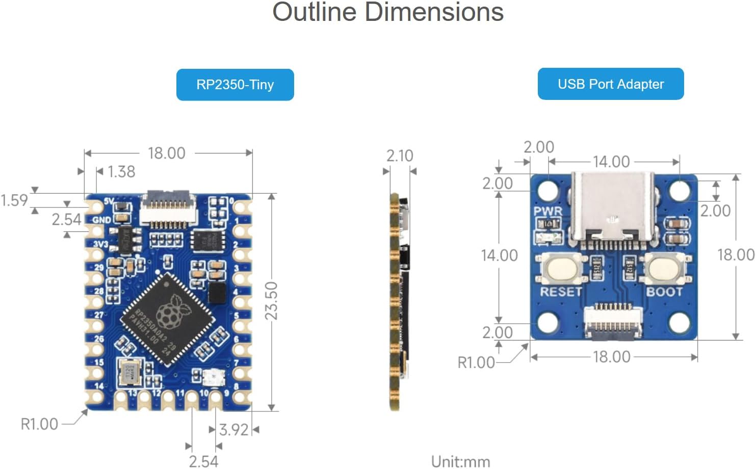
Image: Detailed outline dimensions for both the RP2350-Tiny development board and the USB Port Adapter, shown in millimeters.
5. Platinenlayout und Komponenten
Understanding the layout of the RP2350-Tiny board is crucial for proper usage. The following diagram identifies key components:

Bild: Eine Draufsicht view of the RP2350-Tiny board with numbered callouts identifying major components such as the FPC connector, voltage regulator, Flash memory, RP2350A chip, and RGB LED indicator.
- FPC connector: 0.5mm pitch 8PIN connector for external connections, typically to the USB adapter.
- ME6217C33M5G: Low dropout regulator, providing up to 800mA output (Max.).
- P25Q32SH-UXH-IR: 4MB NOR-Flash memory for program storage.
- RP2350A: The main dual-core, dual-architecture microcontroller chip.
- WS2812: RGB LED indicator for visual feedback.
GPIO Pinout
The RP2350-Tiny features 28 multi-function GPIO pins. The pinout diagram below illustrates the available pins and their primary functions.
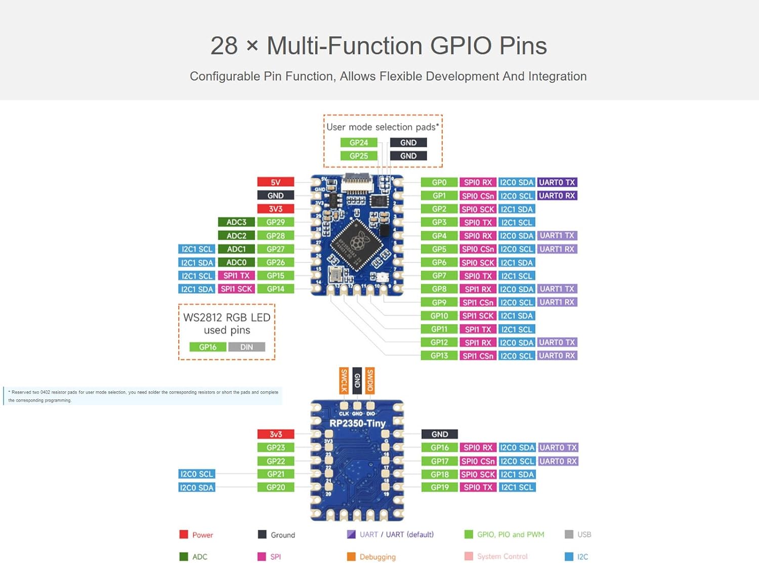
Image: A detailed diagram showing the GPIO pinout of the RP2350-Tiny board, including power, ground, UART, SPI, I2C, ADC, and PWM functions, along with user mode selection pads.
6. Einrichtungsanweisungen
6.1 Connecting the USB Port Adapter
The RP2350-Tiny development board connects to a host computer via the provided USB Port Adapter and FPC cable.
- Carefully connect one end of the FPC cable to the 8-PIN FPC connector on the RP2350-Tiny board. Ensure the cable is inserted correctly with the contacts facing the appropriate direction.
- Connect the other end of the FPC cable to the corresponding 8-PIN FPC connector on the USB Port Adapter.
- Plug the USB Type-C end of the USB Port Adapter into your computer.
Upon successful connection, the board should be recognized by your computer, typically as a mass storage device for drag-and-drop programming.
6.2 Einrichtung der Softwareumgebung
To develop applications for the RP2350-Tiny, you will need to set up a development environment. The board supports C/C++ and MicroPython.
- For C/C++ Development: Utilize the Pico C/C++ SDK. This SDK can be used from the command line or integrated with popular development environments like Visual Studio Code and Eclipse. Refer to the official Raspberry Pi Pico documentation for detailed setup instructions.
- For MicroPython Development: MicroPython is a full implementation of the Python 3 programming language optimized for embedded hardware. You can flash a MicroPython firmware to the board and then use a serial terminal or an IDE like Thonny for programming.

Image: An illustration showing the support for C/C++ SDK and MicroPython development environments for the RP2350-Tiny board.
7. Operating the RP2350-Tiny
7.1 Programming via USB (Drag-and-Drop)
The RP2350-Tiny supports drag-and-drop programming, which is a convenient way to upload firmware or MicroPython scripts.
- With the board connected to your computer via the USB Port Adapter, press and hold the BOOTSEL button on the USB Port Adapter while plugging it into your computer (or press BOOTSEL and then RESET if already connected).
- The board will appear as a mass storage device (e.g., "RPI-RP2").
- Drag and drop your compiled firmware (.uf2 file for C/C++ or .py file for MicroPython) onto this drive.
- The board will automatically reboot and run the new program.
7.2 GPIO Usage
The 28 multi-function GPIO pins can be configured for various purposes, including digital input/output, analog input (ADC), serial communication (SPI, I2C, UART), and Pulse Width Modulation (PWM).
- Refer to the GPIO pinout diagram in Section 5 for pin assignments.
- When programming, ensure that the correct pin numbers and functions are specified in your code.
- Be mindful of voltage levels; the RP2350-Tiny operates at 3.3V logic.
7.3 Energieverwaltung
The RP2350-Tiny supports low-power sleep and dormant modes to conserve energy in battery-powered applications. Consult the RP2350A datasheet and SDK documentation for details on implementing these power-saving features in your code.
8. Wartung und Pflege
- Handhabung: Always handle the development board by its edges to avoid touching components, especially the pins, which can be sensitive to electrostatic discharge (ESD).
- Lagerung: Store the board in an anti-static bag when not in use, in a cool, dry environment.
- Reinigung: Reinigen Sie die Platine bei Bedarf vorsichtig mit einer weichen, trockenen Bürste oder Druckluft. Vermeiden Sie die Verwendung von Flüssigkeiten oder Scheuermitteln.
- Stromversorgung: Ensure a stable 5V power supply when connecting via USB. Over-voltage kann die Platine beschädigen.
9. Fehlerbehebung
- Platine wird vom Computer nicht erkannt:
- Ensure the FPC cable is securely connected to both the RP2350-Tiny and the USB Port Adapter.
- Versuchen Sie es mit einem anderen USB-Kabel oder einem anderen USB-Anschluss an Ihrem Computer.
- Verify that you are holding the BOOTSEL button while connecting the USB adapter to enter mass storage mode.
- Program not running after upload:
- Confirm that the correct .uf2 or .py file was dragged to the "RPI-RP2" drive.
- Check your code for errors.
- Ensure the board automatically rebooted after the file transfer. If not, manually reset the board.
- Peripherals (e.g., I2C, SPI) not working:
- Double-check your wiring against the GPIO pinout diagram.
- Verify that the correct GPIO pins are initialized and configured in your software.
- Ensure external components are properly powered and connected.
- Das Board heizt sich auf:
- Stromzufuhr sofort unterbrechen.
- Check for short circuits on the board or in your external connections.
- Stellen Sie sicher, dass die Eingangslautstärketage is within the specified range (5V via USB).
10. Technischer Support und Ressourcen
For further assistance, online development resources, and technical support, please refer to the Waveshare official website or contact their support team. Detailed documentation, examples, and community forums are often available to help with advanced projects and specific issues.
Weitere Ressourcen und Kontaktinformationen finden Sie auf der Waveshare Store auf Amazon.


