1. Einleitung
This manual provides detailed instructions for the installation, operation, and maintenance of your SINOTIMER DC/AC 24V Digital Programmable Timer Switch, Model 24VDC. This device is designed for precise, programmable control of electrical circuits, offering up to 28 ON/OFF events per day across a 7-day cycle. Please read this manual thoroughly before use to ensure proper function and safety.

Image 1.1: The SINOTIMER 7 Day Digital Programmable Timer Switch.
2. Sicherheitshinweise
- Elektrische Gefahr: Installation and wiring should only be performed by qualified personnel. Ensure power is disconnected before any installation or maintenance.
- Bandtage Kompatibilität: This device operates on DC/AC 24V. Connecting to an incorrect voltage supply may damage the unit and pose a safety risk.
- Tragfähigkeit: Do not exceed the maximum load rating of 10A at 250VAC (2000 watts). For higher loads, use an external contactor or relay.
- Umfeld: Install the timer in a dry, protected environment. While the unit has some dustproof features, direct exposure to water or extreme temperatures should be avoided.
- Batterie: The internal battery is for memory backup only. Do not attempt to charge or replace it unless specified in the maintenance section.
3. Packungsinhalt
Überprüfen Sie, ob alle Artikel im Paket vorhanden sind:
- 1x SINOTIMER Digital Programmable Timer Switch (Model: 24VDC)
- 1x Montagehalterung
- 1x Staubschutz
- 1x CR2032 Battery (pre-installed or separate)
- 1x Disassembly Tool (small screwdriver)
- 2x Befestigungsschrauben
- 5x Spade Connecting Wires
- 1x Benutzerhandbuch (dieses Dokument)
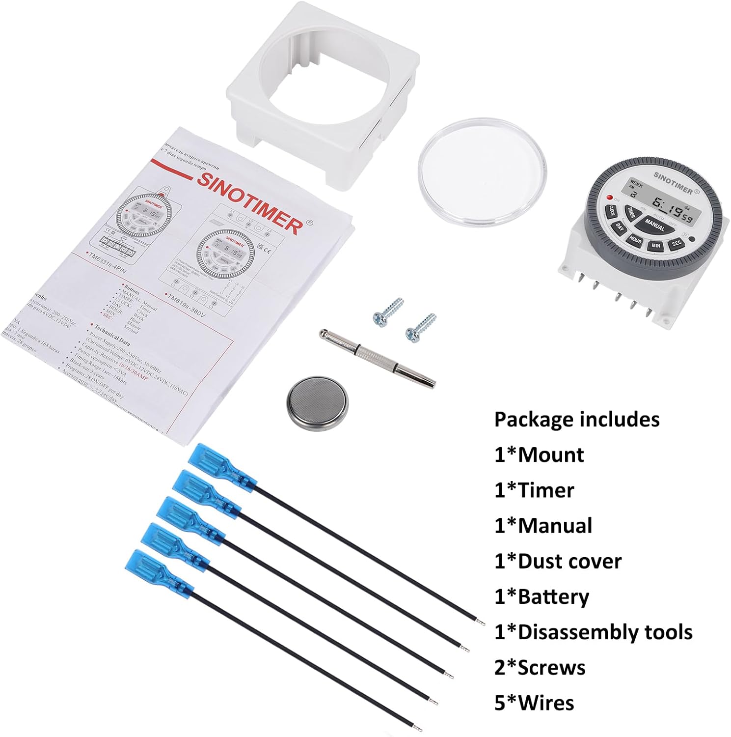
Image 3.1: Visual representation of the package contents, including the timer, mount, manual, dust cover, battery, disassembly tool, screws, and wires.
4. Produktüberschreitungview & Eigenschaften
The SINOTIMER DC/AC 24V Digital Programmable Timer Switch is a versatile device designed for automating various electrical applications. Its compact design and digital display ensure ease of use and integration into control panels.
Hauptmerkmale:
- 7-Tage-Programmierbarkeit: Allows for up to 28 ON/OFF events per day, with flexible programming blocks for daily, weekly, or custom schedules.
- Digitaler Bildschirm: Clear LCD for time, day, and program status.
- Interne Batterie-Notstromversorgung: Retains program settings during power outages.
- SPDT Output: Single Pole Double Throw relay output (1 Normally Open + 1 Normally Closed contact).
- Hohe Tragfähigkeit: Rated for up to 10A at 250VAC, 2000 watts.
- 12/24-Stunden-Format: Vom Benutzer wählbares Zeitanzeigeformat.
- Staubdichtes Design: Enhanced durability for various environments.

Bild 4.1: Überview of the timer's key features, including its robust design and advanced functionality.
5. Spezifikationen
| Besonderheit | Spezifikation |
|---|---|
| Modell | 24VDC (TM-619) |
| Eingangslautstärketage | Gleich-/Wechselspannung 24 V |
| Ausgabetyp | SPDT (1NO+1NC) |
| Maximaler Laststrom | 10A @ 250VAC, 2000W |
| Programmierbare Ereignisse | Bis zu 28 EIN/AUS-Zyklen pro Tag |
| Zeitformat | 12-Stunden-/24-Stunden-Anzeige wählbar |
| Batterie-Backup | Internal CR2032 (for program memory) |
| Abmessungen (T x B x H) | 1.77" x 2.83" x 2.83" (45 mm x 72 mm x 72 mm) |
| Gewicht | 5.3 Unzen (ca. 150 g) |
| Material | Metall, Kunststoff |

Image 5.1: Dimensional drawing and terminal layout of the timer switch.
6. Installation & Verkabelung
WARNUNG: Disconnect all power before installation to prevent electric shock or equipment damage.
6.1 Montage
- Select a suitable location for mounting, ensuring it is protected from moisture and excessive heat.
- Attach the mounting bracket to a flat surface using the provided screws.
- Slide the timer switch into the mounting bracket until it clicks securely into place.
- Optionally, install the clear dust cover over the timer face for added protection.
6.2 Verdrahtungsanweisungen
The timer switch features 5 spade connecting terminals. Refer to the wiring diagram below and the labels on the back of the unit for correct connections.
- Terminals 1 & 2: Power Input (DC/AC 24V). Connect your 24V power supply here.
- Terminal 3: Gemeinsamer Anschluss (COM) für den Relaisausgang.
- Terminal 4: Normally Open (NO) contact for the relay output. The circuit connected here will be ON when the timer is active.
- Terminal 5: Normally Closed (NC) contact for the relay output. The circuit connected here will be OFF when the timer is active.

Image 6.1: Simplified wiring diagram for the timer switch.

Abbildung 6.2: Beispielample of spade connectors attached to the timer terminals.
7. Bedienungsanleitung
After successful installation and power connection, the timer display should illuminate. If not, ensure power is supplied correctly and the internal battery is properly seated.
7.1 Ersteinrichtung (Erstverwendung)
- Zurücksetzen: Press the 'R' (Reset) button with a pointed object (e.g., the provided disassembly tool) to clear all previous settings. The display will show '0:00'.
- Aktuelle Uhrzeit einstellen:
- Drücken Sie die UHR Taste.
- Drücken TAG to select the current day of the week (Mo, Tu, We, Th, Fr, Sa, Su).
- Drücken STUNDE um die aktuelle Stunde einzustellen.
- Drücken MIN um die aktuelle Minute einzustellen.
- Drücken SEC to set the current second (optional, for precise synchronization).
- To switch between 12-hour (AM/PM) and 24-hour format, press UHR Und TAG gleichzeitig.
7.2 Programmierung von EIN/AUS-Ereignissen
Der Timer unterstützt bis zu 28 EIN/AUS-Programme. Jedes Programm besteht aus einer EIN-Zeit und einer AUS-Zeit.
- Drücken Sie die TIMER button. The display will show '1 ON'. This is the first ON program.
- Drücken TAG to select the day(s) for this program. You can choose a single day, weekdays, weekends, or various combinations. Keep pressing TAG , um durch die Optionen zu blättern.
- Drücken STUNDE um die gewünschte Einschaltzeit einzustellen.
- Drücken MIN die gewünschte Einschaltzeit einstellen.
- Drücken TIMER again. The display will show '1 OFF'. This is the first OFF program.
- Wiederholen Sie die Schritte 2-4, um den/die gewünschten Aus-Tag(s), die Stunde und die Minute für dieses Programm festzulegen.
- Drücken Sie weiter TIMER um die Modi '2 EIN', '2 AUS' bis '28 EIN', '28 AUS' durchzuschalten und jedes Programm nach Bedarf einzustellen.
- Nachdem Sie alle gewünschten Programme eingestellt haben, drücken Sie die Taste UHR button to return to the current time display. The programs are now saved.
7.3 Manuelle Übersteuerung
Der HANDBUCH button allows you to override the programmed schedule temporarily or permanently.
- Drücken HANDBUCH um die folgenden Modi durchzuschalten:
- AUF: Output is continuously ON, ignoring programs.
- AUTO EIN: Output is currently ON, following programs.
- AUTOM. AUS: Output is currently OFF, following programs.
- AUS: Output is continuously OFF, ignoring programs.
- Wählen AUTO EIN or AUTO AUS to resume programmed operation.
8. Wartung
8.1 Reinigung
Wischen Sie das Gerät mit einem weichen, trockenen Tuch ab. Verwenden Sie keine Scheuer- oder Lösungsmittel.
8.2 Batteriewechsel
The internal CR2032 battery provides backup for program memory. If the display becomes dim or programs are lost during power outagJa, möglicherweise muss die Batterie ausgetauscht werden.
- WARNUNG: Disconnect main power to the timer before replacing the battery.
- Suchen Sie das Batteriefach auf der Rückseite des Geräts.
- Öffnen Sie vorsichtig den Fachdeckel.
- Nehmen Sie die alte CR2032-Batterie heraus und setzen Sie eine neue ein. Achten Sie dabei auf die richtige Polarität (+ Seite nach oben).
- Schließen Sie den Batteriefachdeckel.
- After replacement, perform an initial setup (Section 7.1) to reset and set the current time.

Image 8.1: Location of the replaceable CR2032 battery.
9. Fehlerbehebung
| Problem | Mögliche Ursache | Lösung |
|---|---|---|
| Der Bildschirm ist leer oder dunkel. | No power supply; Incorrect wiring; Dead internal battery. | Check 24V power input (Terminals 1 & 2). Verify wiring. Replace CR2032 battery. |
| Programs are not running | Timer is in Manual ON/OFF mode; Incorrect program settings; Incorrect current time. | Drücken HANDBUCH until 'AUTO ON' or 'AUTO OFF' is displayed. Review program settings (Section 7.2). Set current time correctly (Section 7.1). |
| Output does not switch ON/OFF | Incorrect output wiring; Load exceeds capacity; Faulty relay. | Verify output wiring (Terminals 3, 4, 5) to your load. Ensure load does not exceed 10A/2000W. If issues persist, contact support. |
| Die Uhrzeit ist ungenau | Internal clock drift; Battery low. | Reset and set time again. Consider replacing the internal battery if drift is significant. |
10. Garantie und Support
For warranty information and technical support, please refer to the documentation provided with your purchase or contact SINOTIMER customer service through the retailer where the product was purchased. Please have your product model (24VDC) and purchase date available when contacting support.
Online-Ressourcen: For additional information, FAQs, or to view other SINOTIMER products, visit the official SINOTIMER store or webWebsite.


