1. Einleitung
The RADIOMASTER XR4 Gemini Xrossband Dual-Band Receiver is designed for remote control applications, offering reliable signal reception through its dual-band capabilities. It supports ExpressLRS Gemini Xrossband (Gem-X) protocol, operating on both 2.4GHz and Sub-G 900MHz frequencies. This manual provides essential information for the proper setup, operation, and maintenance of your XR4 receiver.
2. Packungsinhalt
Bitte überprüfen Sie, ob alle unten aufgeführten Artikel in Ihrem Paket enthalten sind:
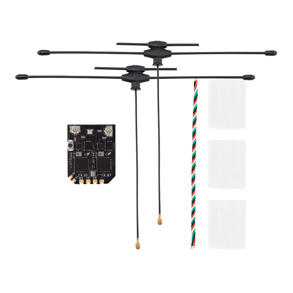
- 1 x XR4 Gemini Xrossband Dual-Band Receiver
- 2 x Dual-Band T-Antenna
- 1 x CRSF-Draht
- 3 x Schrumpfschlauch

This image displays the Radiomaster XR4 receiver board with its two dual-band T-antennas attached, illustrating the complete receiver assembly.
3. Funktionen
- True Diversity & Dual-Band: Utilizes dual LR1121 RF transceivers for enhanced reliability.
- ExpressLRS Gemini Xrossband (Gem-X) Compatible: Supports 2.4GHz and Sub-G 900MHz bands.
- Hochleistungs-Mikrocontroller: Equipped with ESP32D4.
- Dual Semtech LR1121 Transceivers: Provides robust signal processing.
- Secondary UART Port: For advanced functionality and future expansion.
- Castled Pads: Facilitates easy soldering.
- Integriertes WLAN-Modul: Simplifies firmware updates and configuration via WebUI
- Ultra-Low Latency & High Refresh Rate: Ensures stable RF link.

This image highlights the two Semtech LR1121 transceivers, which are central to the receiver's dual-band and true diversity capabilities.

Dieses Bild zeigt eine detaillierte Ansicht. view of the XR4 receiver board, specifically pointing out the additional UART port available for future expansion and advanced functionality.
4. Spezifikationen
| Parameter | Wert |
|---|---|
| MCU | ESP32D4 |
| RF-Chip | LR1121 x 2 |
| HF-Anschluss | IPEX-1 x 2 |
| Antenne | Dual-Band T Antenna x 2 (Included) |
| Frequenzbereich | 2.4GHz / Sub-G 900MHz |
| Telemetrieleistung | 100 mW |
| Maximale Empfangsaktualisierungsrate | DK500Hz / K1000Hz |
| Minimale Empfänger-Aktualisierungsrate | 50 Hz |
| Arbeitsvolumentage | DC 4.5-8.4V |
| Gewicht (ohne Antenne) | 1.7g |
| Maße | 22 mm x 18 mm x 4 mm |
| Firmware Version (pre-installed) | ExpressLRS v3.5.1 |
| FW-Ziel | RadioMaster XR4 2.4/900 Gemini RX |
| Busschnittstelle 1 | CRSF |
| Busschnittstelle 2 | UART |
Dieses Bild bietet eine klare Draufsicht. view of the XR4 receiver's circuit board, showing component layout and connection points.
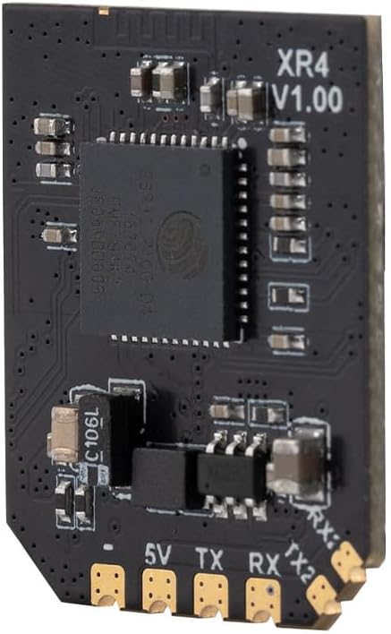
Dieses Bild zeigt eine Seitenansichtfile of the XR4 receiver board, with "XR4 V1.00" clearly visible, indicating the model and version.
5. Einrichtung und Installation
5.1 Kabelverbindungen
The XR4 receiver uses standard CRSF protocol for communication. Connect the receiver to your flight controller or other compatible device using the provided CRSF wire. Ensure correct polarity for power connections (DC 4.5-8.4V).
- 5V: Power input (4.5-8.4V DC)
- Masse: Boden
- Sender: CRSF Transmit (connect to RX on flight controller)
- Empfang: CRSF Receive (connect to TX on flight controller)
- TX2/RX2: Secondary UART port for advanced functionality.
5.2 Antenneninstallation
Connect the two dual-band T-antennas to the IPEX-1 connectors on the receiver board. Position the antennas at a 90-degree angle to each other for optimal signal diversity. Use the provided heat-shrinkable tubes to secure and protect the antenna connections.
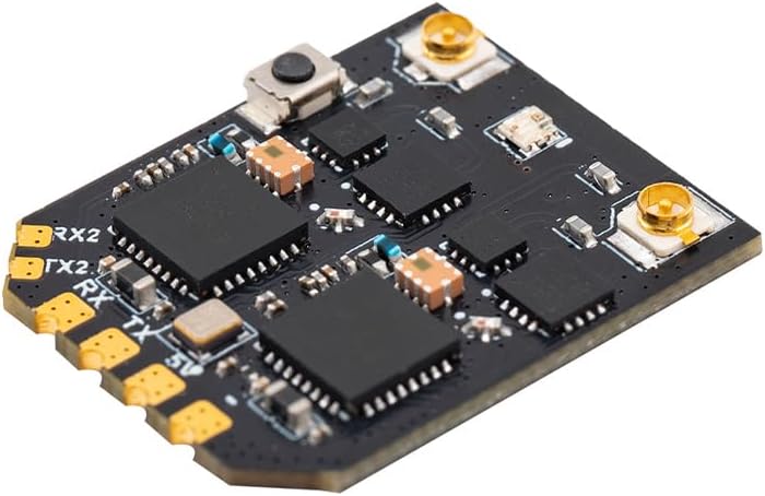
Dieses Bild zeigt eine schräge Ansicht. view of the XR4 receiver board, highlighting the IPEX-1 antenna connectors and the soldering pads for power and CRSF communication.
6. Bedienungsanleitung
6.1 Binding Procedure (ExpressLRS)
The XR4 receiver comes pre-installed with ExpressLRS v3.5.1 firmware. To bind the receiver to your ExpressLRS transmitter module, follow these general steps:
- Ensure your transmitter module is running a compatible ExpressLRS firmware version.
- Power on the receiver. It will enter binding mode if it does not find a valid link. The LED on the receiver will typically flash rapidly.
- On your ExpressLRS transmitter, initiate the binding process. This is usually done via the Lua script or a dedicated bind button/menu option.
- Nach erfolgreicher Kopplung leuchtet die LED am Empfänger dauerhaft, was eine erfolgreiche Verbindung signalisiert.
- If binding fails, ensure your transmitter and receiver have matching ExpressLRS firmware versions and binding phrases (if configured).
6.2 Operating Modes: Gemini and Xrossband (Gem-X)
The XR4 receiver supports various operating modes, leveraging its dual RF circuits:
- Gemini 2.4GHz: Uses two 2.4GHz antennas for dual-frequency operation within the 2.4GHz band.
- Gemini Sub-G 900MHz: Uses two 900MHz antennas for dual-frequency operation within the Sub-G 900MHz band.
- Xrossband (Gem-X): Utilizes one Sub-G 900MHz antenna and one 2.4GHz antenna for dual-band operation, providing enhanced reliability across different frequency ranges.
The specific mode is typically configured via the ExpressLRS Lua script on your transmitter or through the receiver's WebUI

This diagram visually explains the different antenna configurations and packet transmission methods for Gemini 2.4GHz, Gemini Sub-G 900MHz, and Xrossband (Gem-X) dual-band modes.
7. Firmware-Updates
The XR4 receiver features an integrated Wi-Fi module for convenient firmware updates and configuration. To update the firmware:
- Schalten Sie den Empfänger ein.
- Connect to the receiver's Wi-Fi hotspot from your computer or mobile device. The network name will typically be "ExpressLRS RX" followed by a unique identifier.
- Öffnen Sie ein web Browser und navigieren Sie zu http://10.0.0.1.
- Verwenden Sie die WebUI to flash new firmware or adjust settings. Refer to the official ExpressLRS documentation for detailed instructions on firmware flashing.
8. Wartung
The XR4 receiver requires minimal maintenance. Keep the device clean and free from dust and moisture. Regularly inspect antenna connections for damage. Ensure proper heat dissipation if operating in enclosed spaces.
9. Fehlerbehebung
- Kein Link/LED blinkt:
- Stellen Sie sicher, dass der Empfänger ordnungsgemäß mit Strom versorgt wird (4.5-8.4 V).
- Verify the transmitter module is powered on and transmitting.
- Check if the receiver is in binding mode (rapid LED flash). If not, re-initiate binding.
- Confirm that the transmitter and receiver are running compatible ExpressLRS firmware versions.
- Check for correct binding phrase if one is set.
- Poor Range/Signal Quality:
- Inspect antennas for damage or improper connection.
- Ensure antennas are positioned optimally (e.g., 90 degrees to each other).
- Check for sources of interference near the receiver or antennas.
- Verify the selected operating mode (Gemini/Xrossband) is appropriate for your setup.
- Empfänger antwortet nicht:
- Check all wiring connections (power, ground, CRSF TX/RX).
- Ensure the flight controller or connected device is configured correctly for CRSF protocol.
- Attempt a firmware re-flash if the receiver is unresponsive.
10. Sicherheitshinweise
- Always ensure correct power polarity before connecting the receiver. Incorrect wiring can cause permanent damage.
- Operate RC equipment responsibly and within legal limits.
- Halten Sie den Empfänger von Wasser, Feuchtigkeit und extremen Temperaturen fern.
- Do not attempt to modify the receiver's hardware beyond specified connection points.
- Sorgen Sie für ausreichende Belüftung, um eine Überhitzung zu vermeiden.
11. Garantie und Support
Informationen zur Garantie und zum technischen Support finden Sie auf der offiziellen RADIOMASTER-Website. webWebsite oder wenden Sie sich an Ihren autorisierten Händler. Bewahren Sie Ihren Kaufbeleg für Garantieansprüche auf.