1. Einleitung
This manual provides detailed instructions for the safe and efficient operation of the Aideepen 1800W 40A DC-DC Boost Converter Power Module. This module is designed to convert a lower DC input voltage (14-85V) to a higher, adjustable DC output voltage (14-120V) with a maximum output power of 1800W and current of 20A. It features constant voltage and constant current capabilities, making it suitable for various applications such as high-power LEDs, motors, digital products, and solar panel regulation.
Zu den Hauptmerkmalen gehören:
- Breite Eingangslautstärketage-Bereich: DC 14-85 V.
- Einstellbare Ausgangslautstärketage: DC 14–120 V.
- Adjustable output current: 1.5-20A (±0.5A).
- High efficiency and stability with optimized circuit design.
- Multi-protection mechanisms: Input reverse polarity protection and undervoltage Schutz.
- Temperature-controlled cooling fan for extended lifespan.
- Replaceable fuses for practical maintenance.
2. Sicherheitshinweise
Bitte lesen und verstehen Sie alle Sicherheitshinweise und Anweisungen, bevor Sie dieses Gerät in Betrieb nehmen. Andernfalls besteht die Gefahr eines Stromschlags, eines Brandes oder schwerer Verletzungen.
- Do not exceed maximum or minimum input/output voltage und Stromgrenzen. Operating outside specified parameters can damage the module and connected devices.
- Avoid short-circuiting the output. Adjusting output current by short-circuiting is strictly prohibited.
- Do not charge supercapacitors directly with this module.
- Ensure the input power supply capacity is at least 1.5 times the load power to prevent instability or damage.
- This module generates heat during operation. Ensure adequate ventilation and do not obstruct the cooling fan.
- Handle with care. This is an exposed circuit board and requires caution to prevent accidental contact with live components.
- Vor jeglichen Anschlüssen oder Einstellungen muss die Stromzufuhr unterbrochen werden.
- Use appropriate wire gauges for input and output connections to handle the expected current.
3. Produktüberschreitungview und Komponenten
The Aideepen 1800W Boost Converter module consists of a main circuit board, heat sink, cooling fan, and various electronic components.
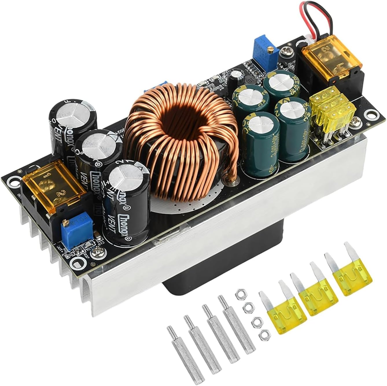
Abbildung 3.1: Oben view of the Aideepen 1800W Boost Converter module, showing the main components including the large inductor, capacitors, heat sink, and terminal blocks. Several yellow fuses and metal standoffs are also visible, indicating included accessories.

Abbildung 3.2: Oben und unten views of the converter module. The top view displays the circuit board layout, while the bottom view clearly shows the integrated cooling fan attached to the heat sink, designed for thermal management.

Figure 3.3: This image shows the main boost converter module, the separate cooling fan, and the included mounting hardware (standoffs and nuts) for installation.

Figure 3.4: Detailed close-up shots of critical components: the replaceable fuses for overcurrent protection, the cooling fan for heat dissipation, and the large inductor coil, which is central to the boost conversion process.
4. Spezifikationen
| Parameter | Wert |
|---|---|
| Modellnummer | GACC0025-007 |
| Eingangslautstärketage Reichweite | Gleichstrom 14 V - 85 V |
| Ausgangsvolumentage Reichweite | DC 14V - 120V (Adjustable) |
| Max. Eingangsstrom | 40 A |
| Ausgangsstrombereich | 1.5A - 20A (Adjustable, ±0.5A) |
| Maximale Ausgangsleistung | 1800 W |
| Umwandlungseffizienz | 90% - 96% (Efficiency varies with input/output voltage Unterschied) |
| Betriebstemperatur | -20°C bis +65°C |
| Schutzfunktionen | Input Reverse Polarity Protection, Input Undervoltage-Schutz |
| Maße | 130 mm x 72 mm x 51 mm (ca. 5.12" x 2.83" x 2.01") |

Figure 4.1: Diagram illustrating the physical dimensions of the boost converter module in millimeters and inches.
5. Einrichtung und Anschlüsse
Before connecting the module, ensure all power sources are disconnected.
- Terminals identifizieren: Locate the input (VIN+, VIN-) and output (OUT+, OUT-) terminals on the module.
- Eingangsanschluss: Connect your DC input power source to the VIN+ (positive) and VIN- (negative) terminals. Ensure correct polarity. The module has reverse polarity protection, but incorrect connection should still be avoided.
- Ausgangsanschluss: Connect your load to the OUT+ (positive) and OUT- (negative) terminals.
- Montage: Use the provided standoffs and nuts to securely mount the module in a well-ventilated area, ensuring the cooling fan has unobstructed airflow.

Figure 5.1: This diagram illustrates the input (VIN+, VIN-) and output (OUT+, OUT-) terminals, along with the adjustment potentiometers for output voltage (CV), output current (CC), and input undervoltage protection (UVP). Indicators for output voltage and overcurrent are also shown.
6. Bedienungsanleitung
The module features three adjustable potentiometers:
- Lebenslauf (Konstante Voltage) Potentiometer: Regelt die Ausgangslautstärketage. Im Uhrzeigersinn drehen, um zu erhöhen, gegen den Uhrzeigersinn, um zu verringern.
- CC (Constant Current) Potentiometer: Adjusts the output current limit. Turn clockwise to increase, counter-clockwise to decrease.
- UVP (Unterbestand)tage Protection) Potentiometer: Adjusts the input undervoltagSchutzschwelle. Im Uhrzeigersinn drehen, um die Schutzschwelle zu erhöhen.tage, gegen den Uhrzeigersinn, um abzunehmen.
6.1. Ausgangsvolumentage Adjustment (CV)
- Connect the input power supply.
- Connect a voltmeter to the output terminals.
- Adjust the CV potentiometer until the desired output voltage erreicht ist.
- Notiz: When setting the output voltage to 120V, the input voltage must be 20V or higher.
6.2. Output Current Adjustment (CC)
- First, set the output voltage (CV) to the desired level.
- Connect an ammeter in series with the output load, or use a suitable electronic load.
- Adjust the CC potentiometer until the desired output current limit is reached.
- Wichtig: Do not adjust the output current by short-circuiting the output terminals. This can damage the module.
6.3. Input Undervoltage Protection Adjustment (UVP)
- Connect the input power supply.
- Adjust the UVP potentiometer to set the desired minimum input voltage. Wenn die Eingangsvoltage drops below this threshold, the module will stop outputting power to protect the input source (e.g., battery).
- The UVP indicator LED will illuminate when undervoltagDer Schutz ist aktiv.
Calculation for Operating Current: Output Power / Input Voltage * 1.06 (1.06 accounts for power loss). Ensure the calculated operating current does not exceed the maximum input current of your power source.
7. Wartung
Regular maintenance helps ensure the longevity and optimal performance of your boost converter module.
- Reinigung: Periodically clean the module, especially the heat sink and fan, to remove dust and debris. Use compressed air or a soft brush. Ensure power is disconnected before cleaning.
- Lüfterbetrieb: The cooling fan is temperature-controlled and will only activate when the heat sink temperature reaches approximately 40°C. This reduces noise and extends fan life. Ensure the fan is spinning freely when active.
- Sicherungswechsel: The module is equipped with replaceable fuses. If a fuse blows, disconnect power, identify the faulty fuse, and replace it with a fuse of the same rating. Spare fuses are included.
- Verbindungen: Periodically check all input and output connections to ensure they are secure and free from corrosion.
8. Fehlerbehebung
| Problem | Mögliche Ursache | Lösung |
|---|---|---|
| Keine Ausgangslautstärketage |
|
|
| Ausgangsvolumentage instabil |
|
|
| Lüfter dreht sich nicht |
|
|
| Burning smell / Smoke |
|
|
9. Garantie und Support
Aideepen provides a 24-month service period for products purchased from Aideepen. If you encounter any quality issues with the item, a new replacement product can be obtained.
For technical support, warranty claims, or any questions regarding the product, please contact Aideepen customer service through the retailer where you purchased the product or visit the official Aideepen store: Aideepen Store on Amazon.


