1. Einleitung
The ABB D13 15-M 65 Modbus is a three-phase energy meter with MID certification, designed for accurate measurement of energy consumption and production in residential and commercial buildings. It offers direct measurement up to 65 A and complies with accuracy class B according to the MID directive, reliably recording active, reactive, and apparent energy. Its 4-quadrant measurement capability makes it suitable for both consumption and feed-in applications. The meter features a digital display for up to seven measured values, a digital input, and a digital output (S0) for flexible applications such as pulse or alarm output. With a compact design of only three division units (52.5 mm), it allows for space-saving installation on DIN rails. The housing is made from 70% recycled plastic, reflecting high sustainability standards.
2. Produktüberschreitungview
2.1 Hauptmerkmale
- Three-phase energy meter with direct measurement up to 65 A and MID certification (accuracy class B).
- 4-quadrant measurement for accurate recording of active, reactive, and apparent energy in consumption and feed-in applications.
- Digital inputs and outputs (1 DI + 1 DO) for flexible use as pulse or alarm output.
- Compact design with only 3 division units (52.5 mm) for space-saving DIN-rail mounting.
- Durable design: housing made of 70% recycled plastic, protection class IP20, operating temperature range from -40 °C to +70 °C.
2.2 Komponenten
The ABB D13 15-M 65 Modbus energy meter includes:
- Digital display for measurement values.
- Control buttons (OK, ESC, HOME, Up/Down arrows).
- Input and output terminals for electrical connections.
- Modbus communication terminals.
- Digital input and output terminals.
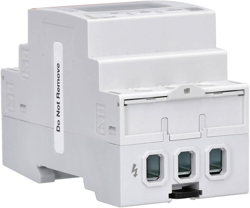
- DIN rail mounting clip.
- Touch protection cover.
3. Spezifikationen
| Attribut | Wert |
|---|---|
| Marke | ADB |
| Technische Daten | 6.5 x 5.25 x 9.7 cm |
| Modellnummer | D13 15-M 65 Modbus |
| Hersteller | ADB |
| Teilenummer | 2CMA241765R1000 |
| Anzahl der Artikel | 1 |
| Im Lieferumfang enthaltene Komponenten | Touch protection cover |
| Schutzklasse | IP20 |
| Betriebstemperaturbereich | -40 °C bis +70 °C |
4. Sicherheitshinweise
Always observe the following safety precautions during installation, operation, and maintenance of the ABB D13 15-M 65 Modbus energy meter:
- Installation und Wartung dürfen nur von qualifiziertem Personal durchgeführt werden.
- Ensure that the main power supply is disconnected before any installation or wiring work.
- Verify all connections according to the wiring diagram to prevent damage to the device or electrical system.
- Do not operate the device if it shows visible signs of damage.
- The device is designed for indoor use within the specified temperature range.
- Use appropriate personal protective equipment (PPE) when working with electrical installations.
5. Installation
The ABB D13 15-M 65 Modbus energy meter is designed for DIN-rail mounting, offering a compact solution for electrical panels. It occupies three division units (52.5 mm) on the DIN rail.
5.1 Montageschritte
- Ensure the power supply to the DIN rail is completely disconnected.
- Hook the top edge of the meter onto the DIN rail.
- Press the bottom edge of the meter firmly until it clicks into place on the DIN rail.
- Verify that the meter is securely fastened and cannot be easily dislodged.
5.2 Schaltplan
Refer to the following diagram for correct wiring connections. Ensure all connections are tight and secure.

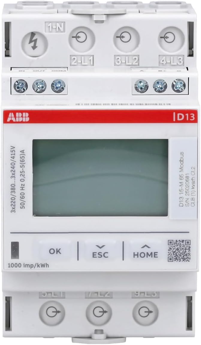
Elektrische Anschlüsse:
- Input Terminals (Top): Connect the incoming three-phase power supply and neutral to terminals 1-N, 2-L1, 3-L2, and 4-L3 respectively.
- Output Terminals (Bottom): Connect the load to terminals 5-L1, 7-L2, and 9-L3.
Modbus Communication Connections:
- Connect Modbus A- to the corresponding A- terminal of the Modbus network.
- Connect Modbus B+ to the corresponding B+ terminal of the Modbus network.
- Connect Modbus C (Common) to the common ground of the Modbus network.
Digital Input/Output Connections:
- Digitaler Eingang (DI): Connect external signals to the IN terminal.
- Digital Output (DO/S0): Use the OUT terminal for pulse or alarm output. Connect the COM terminal as the common reference.
6. Bedienungsanleitung
The ABB D13 15-M 65 Modbus energy meter features a digital display and control buttons for easy navigation and viewing of measured values.
6.1 Displaynavigation
Use the following buttons to navigate through the display menus and view different parameters:
- OK-Taste: Bestätigt die Auswahl oder ruft Untermenüs auf.
- ESC-Taste: Exits the current menu or cancels an operation.
- Home "Button: Kehrt zum Hauptanzeigebildschirm zurück.
- Pfeiltasten nach oben/unten: Scrolls through available measurement values or menu options.
The display can show up to seven different measurement values, including active energy, reactive energy, apparent energy, voltage, current, frequency, and power factor.
6.2 Modbus-Kommunikation
The meter supports Modbus RTU communication for integration into building management systems or other monitoring platforms. For detailed information on Modbus registers and communication protocols, refer to the 'D11 15 - D13 15 Kommunikationshandbuch' document, which can typically be found on the ABB support webWebsite.
Modbus Parity Settings: The meter offers various parity settings. For Modbus RTU, 'none156' typically refers to no parity with one stop bit, and 'none256' refers to no parity with two stop bits. The standard for Modbus is often no parity with two stop bits.
7. Wartung
The ABB D13 15-M 65 Modbus energy meter requires minimal maintenance. Regular inspection and cleaning are recommended to ensure optimal performance.
- Reinigung: Reinigen Sie die Außenseite des Zählers mit einem weichen, trockenen Tuch. Verwenden Sie keine Scheuermittel oder Lösungsmittel.
- Inspektion: Überprüfen Sie regelmäßig alle elektrischen Verbindungen auf festen Sitz und Anzeichen von Verschleiß oder Beschädigung.
- Umfeld: Um Schäden zu vermeiden, muss sichergestellt werden, dass die Betriebsumgebung innerhalb der vorgegebenen Temperatur- und Feuchtigkeitsbereiche bleibt.
8. Fehlerbehebung
This section provides solutions to common issues encountered with the ABB D13 15-M 65 Modbus energy meter.
| Problem | Mögliche Ursache | Lösung |
|---|---|---|
| Display not working or segments missing | Defective display or power issue. | Check power supply. If power is present and display is still faulty, contact ABB support for replacement or service. |
| Buttons unresponsive or require excessive force | Mechanical issue with buttons. | Ensure buttons are pressed firmly and directly. If the issue persists, contact ABB support. |
| Modbus communication failure | Incorrect wiring, incorrect parity settings, or incorrect Modbus address. | Verify Modbus wiring (A- to A-, B+ to B+). Check Modbus parity settings (e.g., none256 for 2 stop bits). Confirm Modbus address is unique and correct. Refer to the 'D11 15 - D13 15 Kommunikationshandbuch' for detailed Modbus register information. |
| Inaccurate energy readings | Incorrect wiring or calibration issue. | Double-check all electrical connections against the wiring diagram. Ensure the meter is correctly configured for the electrical system. If the problem persists, contact ABB support. |
9. Garantie und Support
For warranty information, technical support, or service requests, please contact your local ABB representative or visit the official ABB website. Keep your product model number (D13 15-M 65 Modbus) and part number (2CMA241765R1000) readily available when contacting support.
10. Ähnliche Videos
No official product videos for the ABB D13 15-M 65 Modbus energy meter were found in the provided data. The available videos are for different product brands (DEWIN, ORNO) and are therefore not included in this manual.


